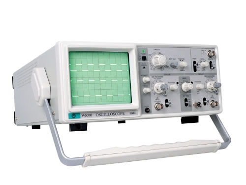
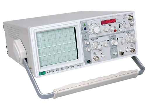
20 MHz (With Frequency Counter) Analog Oscilloscope
Description
Analog oscilloscope is used to observe the change of an electrical signal over time. It uses electronic gun to emit electrons to the screen. The emitted electrons form into electron beam by focusing. Then the electron beam is irradiated to the screen coated with fluorescent material and gives out light. It shows the signal waveform by inputting signal which controls the deflection of electron beam. This 20 MHz analog oscilloscope is equipped with frequency counter.
Application
It is widely used in science, pharmacy, engineering and telecommunication industries.
Advantages
1. It is simple to operate. All the operation processes are completed in the faceplate so that the waveform responses in a quick manner.
2. 20 MHz analog oscilloscope has high vertical resolution which is also continuous and unlimited.
3. It is fast in data update because it captures hundreds and thousands of waveforms per minute.
4. It provides visible waveforms to the technicians who can take tests easily within the regulated bandwidth.
Parameters
| CRT | ||
| Screen | 6" screen with internal graticule: 8×10 divisions (1 division=1cm) | |
| Accelerating Voltage | +1.9kv | |
| Phosphor | P31 standard | |
| Focusing | Adjustable | |
| Trace Rotation | Adjustable | |
| Intensity Control | Provided | |
| Vertical Deflection | ||
| Bandwidth | DC Coupling | DC to 20MHz (Normal) DC to 7MHz (Magnified) |
| AD Coupling | 10Hz to 20MHz (Normal) 10Hz to 7MHz (Magnified) | |
| Deflection Factor | 5mV/div to 5V/div in 10 steps of 1-2-5 sequence (X5 Magnified: 1mV/div to 1V/div in 10 steps) | |
| Display Mode | CH1, CH2, ADD, ALT, CHOP | |
| Accuracy | Normal: ±3%, Magnified: ±5% | |
| Input Impedance | 1MΩ, 25pF | |
| Max. Input Voltage | 250V (DC+AC peak) | |
| CH1 Output | 20mV/div (in 50Ω, 20Hz to 10MHz) | |
| Rise Time | ≤17.2ns | |
| Polarity Inversion | CH2 Only | |
| Horizontal Deflection | ||
| Time base | 0.2μs/div to 0.2s/div in 9 steps of 1-2-5 sequence. | |
| Sweep Magnification | X10 | |
| Accuracy | Normal: ±3%, Magnified: ±5% | |
| X-Y Mode | ||
| X-Axis | CH1 (Bandwidth: DC-500kHz) | |
| Y-Axis | CH2 | |
| X-Y Phase Difference | 3° or less (DC-50kHz) | |
| Trigger System | ||
| Mode | NORM, AUTO, TV-V, TV-H | |
| Trigger Source | CH1,CH2,VERT, LINE, EXT | |
| Coupling | AC | |
| Slope | + or - | |
| Sensitivity & Frequency | 0.5 div (0.5Vp-p EXT), 10Hz-20MHz 1.0 div or 1Vp-p, TV | |
| Frequency Meter | ||
| Measurement Range | 0-30MHz | |
| Sensitivity | ≤50mV | |
| Calibrator | ||
| Frequency | 1kHz ±20% | |
| Voltage | 0.5V ±10% | |
| Power Supply | ||
| Voltage Range | 220V/110V ±10% | |
| Fuse | 0.5A/1A | |
| Frequency | 50Hz-60Hz | |
| Physical | ||
| Dimensions | 310(W) × 130(H) × 370(D) mm | |
| Weight | 9kg | |
Notes
1. 20 MHz analog oscilloscope with frequency counter should be equipped with suitable line voltage.
2. To avoid electrical shock, the protective grounding conductor of power cord should be connected to ground.
Maintenance
1. To maintain good ventilation, regular cleaning should be carried out.
2. Do not spray cleaner directly onto the instrument when cleaning it. Use a soft cloth with mild detergent and water instead.

- 30 MHz Analog OscilloscopeAnalog oscilloscope, which employs cathoderay tubes to display a waveform, is the first oscilloscope that is used by engineers. The screen’s photoluminescent phosphor illuminates every time an electron hits it. A representation of signal is displayed as successive bits of phosphor light up, while a trigger makes the displayed waveform appear stable. Upon completing...


